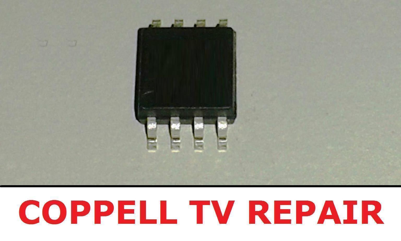
Lately I’ve had a ‘fun’ experience with my LG 31MU97-B 4K monitor not turning on. The night before, I unplugged it from the wall due to an oncoming storm and the next day it just wouldn’t turn on. This is a known problem with this monitor where the IC205 chip on the monitor becomes stuck in a state which doesn’t respond to button presses.
Fortunately I found an extremely useful blog which helped me solve the issue!
Find the original link including user comments (which are also very helpful) here:
Integer13 WordPress
My experience was a little different and I used a combination of methods from the original author and the user comments. Below is how you can either temporarily fix or repair your LG monitor.
What you need:
The IC chip I bought was from ‘coppelltvrepair’ on eBay:
Coppell Tv Repair
(The shipping to Australia is outright theft at $29 for a part that weights basically nothing, but it worked… and I saved money I would have spent on a new screen)

Or if that listing has expired, search for “LG 31MU97-B MAIN BOARD 62882801 / 31MU97/LM41C / EAX66105904 EEPROM IC205”
If you’re soldering the chip you will need:
● The new IC205 Chip
● A Fine-Tipped Soldering Iron
● Desoldering Braid
● A very narrow flat-headed screwdriver
● Very Fine Solder (0.3-0.7mm)
● Soldering Flux
● Isopropyl Alcohol
● A Cleaning Cloth
To Jump Start or Fix the Monitor:
DISASSEMBLING THE MONITOR
1. Turn off and unplug all the cables in the monitor and take it off the stand.
2. Remove the backing by levering the tabs on the back of the monitor all the way around. There is a big sticky pad in the middle on the back which can be slowly pried off with something like a ruler.
3. Unscrew the metal motherboard casing and take out the switch and speakers as well as the sticky tape that’s holding down the wires.
4. Flip over the metal casing while leaving all the wires and ribbon cables connected. Some wires may need to be taken out of the plastic wire holders to give you enough length to flip the casing over.
At this point you should rest the monitor on a box or something so that when it turns on you can change the settings as required in step 11.

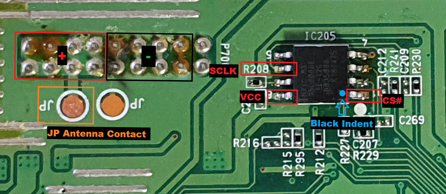
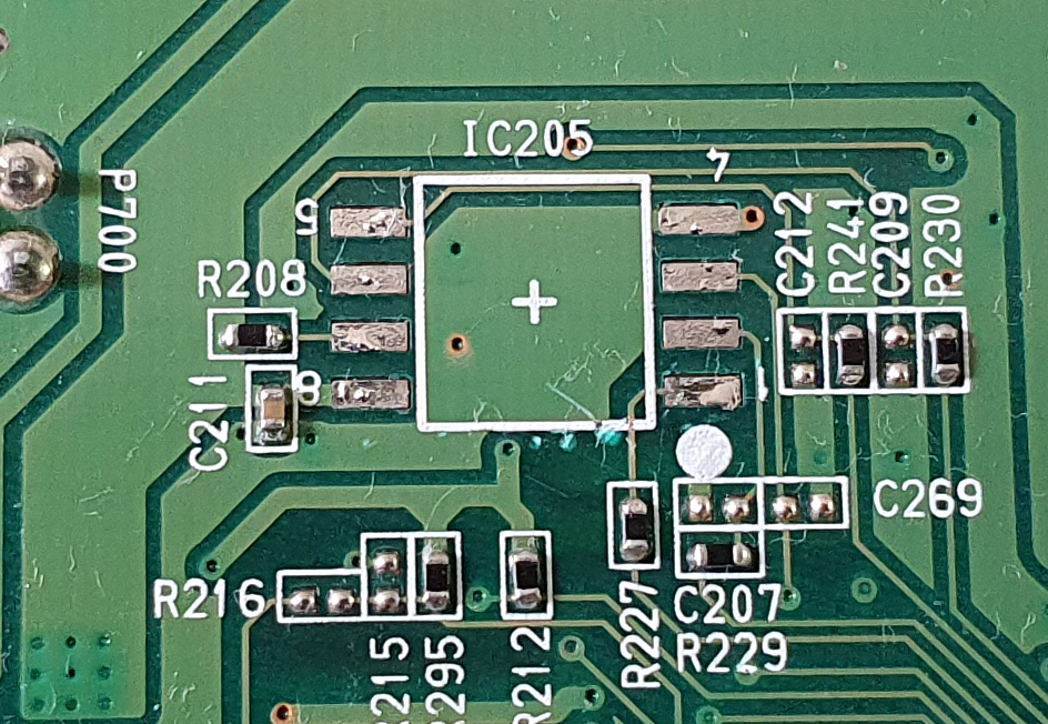
5. You will see the IC205 chip at the edge where the ribbon cables are connected. Have a look at the image above, or head to the link at the top of this post and familiarize yourself with the diagram. At this point you should also cover up the power board on the left with the plastic backing of the monitor or something else non-conductive so you don’t slip and touch any part of that board.
6. Unplug and switch off the monitor’s power button (If it’s not already) then plug in the power cable and turn the switch on again. You should put the power cable through the plastic backing casing so you can reassemble it later without having to unplug it or turn it off. (Doing this is the best option to keep it working if you aren’t planning on buying a replacement chip, because as soon as it loses power it won’t turn on again)
TESTING THE MONITOR AND BOOTING IT UP
7. Using a multimeter on the DC voltage reading mode on setting 200 (or so), hold the positive (red) lead on the ‘JP’ to the left of the chip with the ‘antennas’ coming out of the top. Then hold the negative (black) lead to the ‘CS#’ prong. The CS# prong is the one nearest to the dot in the corner of the chip.
I recommend AGAINST doing what the article above says by touching the positive (red) lead to the array of positive terminals right next to the negative ones. You can easily slip and hit the wrong one creating a spark if not done correctly. (If you do create a spark like I did, you ‘should’ be fine and there (hopefully) won’t be any damage to the monitor. Again, as per step 5 make sure the power board to your left is covered by something before attempting this step, you will electrocute yourself if you touch it and cause irreversible damage if you short circuit any part of it.
Alternatively, (and the most highly recommended) you can use a 1k resistor to connect the ‘CS#’ and ‘VCC’ legs of the chip to bring it to life. The VCC leg is the one opposite to the CS# leg. This method also saves you buying a multimeter if you don’t have one.
8. While holding the multimeter (or resistor) in place, flick the power button on the monitor next to the power cable. (You may need two people for this step and the next one)
9. While still holding the multimeter (or resistor) in place, press the toggle power button on the monitor every second or so until you hear the beeps of it turning on. You will also see the back of the monitor’s backlight glow when it turns on.
If you don’t hear any beeps after a minute or so, unplug the cable and head back to step 6 and repeat until you hear it turn on.
10. As soon as you hear the startup beeps, remove the multimeter’s prongs.
11. Use the control joystick to go into many of the settings and change them, including input method, volume, brightness and enabling/disabling PBP (picture by picture). This will help the chip to ‘remember’ the state it is in, if you do turn it off. (This only lasts a short duration once you turn the screen off) This step isn’t foolproof so don’t rely on it to work. If you aren’t soldering the new chip in place I recommend just reassembling the monitor without turning it off by the switch or by pulling out the power plug.
Turn the screen off (every time) by holding the power button for a few seconds or by going through the screen’s menu until it’s off (press in then 2 seconds later pushing it towards the side the light glows from). Although you can continue with the following steps without turning it off at all.
SOLDERING THE NEW IC205 CHIP
12. This is the point where you would replace the IC205 chip if you have one. You need a very steady hand and an eye for detail and possibly an assistant. MAKE SURE THE MONITOR IS OFF AND UNPLUGGED BEFORE SOLDERING ANY PART OF IT! If you aren’t replacing the chip, skip this step.
a) First desolder the current chip using a desoldering band by heating up each leg of the chip and running the band over it to soak it up. Once desoldered, my chip needed a bit of a levering with a very narrow flat head screwdriver to get it to quite literally pop off the board. You will need a fine soldering iron tip for this purpose. Make sure you remember which side the black circular indent on the chip is facing as this is how you will align the new chip.
b) Once the chip is off remove any remainder solder on the board with the desoldering band.
c) Clean the board using isopropyl alcohol and a cloth.

d) Cover the area with soldering flux to help the solder to stick.
e) Using very fine solder (0.5-0.77mm) melt a tiny amount to any two opposite corners of the board where the chip will go. You only need the tiniest amount of solder for this purpose. If you add too much, use the desoldering band to remove some.
f) Hold the new chip in place making sure the dot is in the correct corner, then melt the corner solder one leg at a time while pushing the chip down so it ends up flush with the board. Make sure the legs of the chip only touch the corresponding contact and that there’s not any two legs joined by solder. Try not to heat up the chip too much.
g) Once the corners are soldered in place you can add tiny amounts of solder to the rest of the legs to make contact with the board.
h) Once the chip is in place you can clean the board with isopropyl alcohol. and leave it to cool for a few minutes.
ASSEMBLING THE MONITOR AGAIN
13. Being very careful, take off the covering from the power side and flip the motherboard housing over, being sure to align the grooves it sits in perfectly as you don’t want to short the monitor on any metal. Check that there’s no wires under the housing as they like to find their way underneath it.
14. Put the speakers and button back in their places. Before you screw in the motherboard housing to the monitor again, slide the plastic backing up to the end of the power cable which is still inserted. If you screwed the metal housing down first you won’t be able to get the plastic casing back on and you’ll have to take the screws out again. (Check if the monitor still turns on and off) You won’t be able to screw in the two back screws, however you can screw in the two top ones by lifting the housing slightly and finger tightening them.
If you aren’t going to replace the IC chip at any point you can use a flame gun to melt away the portion of the plastic under where the power cable is inserted so you can screw in all the screws. Be warned that the resale value will drop significantly, and wear a mask so you don’t inhale the toxic plastic fumes! When you’ve melted a portion and it’s pliable, use a stick or something to remove the plastic before it re-hardens. Also make sure that it’s relatively flat when you’re done or you may not be able to get the monitor backing on again. (Even though it’s included – I don’t recommend doing this part of the step unless you desperately want a working monitor again)
15. Don’t clip the plastic casing back on (unless you are sure you won’t be opening it again). Screw in the top two (or a top and a bottom screw) on the back of the monitor again to secure the plastic backing onto the screen.
16. Put the monitor back on the stand, plug in the data cable and check if it still works. If it does then woohoo! This method will keep the monitor working until you get the replacement chipset. Therefore I recommend connecting a UPS between the wall and the monitor to safeguard it against future power failures.


